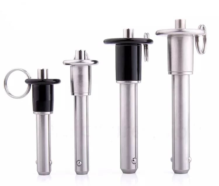
TL;DR: A ball lock pin is a quick-release fastener that uses spring-loaded balls to lock into a mating hole. The internal mechanism is three parts: a central plunger, a compression spring, and two or more locking balls. It stays locked because the plunger’s internal ramp angle is shallow enough that external force on the balls can’t back-drive the spring. Axial retention typically sits between 200 and 500 lbf. Shear can exceed 5,000.
The Three Components Doing All the Work
A ball lock pin contains three internal components: a plunger, a compression spring, and two locking balls. These sit inside a hollow outer sleeve, which is the main shaft of the pin.
The plunger is a central rod running the length of the pin. At its lower end it has a specific profile, usually a thick section tapering down to a narrower waist. A compression spring sits beneath the handle and keeps the plunger pushed downward in its default state.
The locking balls sit in precision-drilled holes near the tip of the outer sleeve. On a standard 1/4-inch pin these balls are typically 3/32-inch (about 2.4mm). The holes in the sleeve are swaged or coined, meaning the outer opening is narrowed slightly so the balls can protrude past the shaft OD without falling out of their seats.
What Happens When You Press the Button
Pressing the button moves the internal plunger, which retracts the locking balls into the shaft. The sequence has four phases.
At rest, the compression spring forces the plunger downward. The thickest part of the plunger sits directly behind the locking balls, wedging them outward against the coined edges.
Press the button and you’re overcoming spring pressure. Actuation force usually runs somewhere in the 3 to 10 lbf range (ballpark 15 to 45N), depending on pin diameter and the spring rating the manufacturer chose. Stroke distance is short, roughly an eighth to a quarter inch.
As the plunger moves, its thick section slides past the balls and the narrow waist aligns with the ball holes. The balls are now free to drop inward. Insert the pin into the mating hole, release the button, and the spring drives the plunger back up. The ramped section of the plunger wedges the balls back outward, locking the pin behind the mating material. That’s the whole cycle.
The Geometry of Self-Locking (Why It Doesn’t Pop Out)
A ball lock pin stays locked because of the cam angle machined into the plunger. When an axial load tries to pull the pin out, the mating material pushes radially inward against the protruding balls.
For the pin to release under that load, the balls would have to shove the plunger downward and compress the spring. They can’t, because the ramp angle on the plunger is shallow, generally under 15 degrees.
That shallow angle creates a self-locking taper. Radial force from the balls against the plunger can’t overcome the static friction plus the mechanical disadvantage of the wedge. The force transfers into the plunger shaft itself instead of back-driving it. The pin releases only when the button is manually pressed and the wedge is removed.
Holding Force vs. Shear Load — Two Very Different Numbers
This is the one that gets people. Shear strength and axial retention are two completely different ratings, and shear is often 10 to 20 times higher than retention. I’ve watched buyers spec a pin off the shear number on a datasheet and then act surprised when the thing walks out of its hole under vibration.
Shear strength measures load applied perpendicular to the pin’s axis, trying to slice the pin in half. Because the outer sleeve is solid metal, shear is high. Axial retention measures the load required to pull the locked pin straight out without pressing the button. That force is limited by the shear capacity of the small protruding balls and the coined edges holding them in. Completely different failure mode, completely different number.
Carr Lane’s catalog illustrates the gap on a common 1/4-inch pin:
| Pin Diameter | Material | Shear Capacity | Axial Retention Force |
|---|---|---|---|
| 1/4″ (0.250″) | 4130 Steel | 4,600 lbs | 230 lbs |
| 1/4″ (0.250″) | 17-4 PH Stainless | 5,300 lbs | 230 lbs |
| 1/2″ (0.500″) | 4130 Steel | 18,400 lbs | 1,160 lbs |
Notice the 4130 and 17-4 pins have identical retention. That’s because retention is governed by the ball/coin geometry, not the base material of the sleeve. Switching to stainless gets you corrosion resistance and a bit more shear. It does nothing for pull-out. If your application is tension-dominant, you probably shouldn’t be using a ball lock pin at all, and I’ll get to that further down.
I still spec 17-4 for most freshwater and marine-adjacent fixturing even when 4130 would be fine on paper. Old habit from aerospace work, not strictly justified by the numbers.
Single-Acting vs. Double-Acting Mechanisms
Single-acting pins have a button at one end and locking balls at the other. Press the button to release. Standard configuration for most industrial tooling.
Double-acting pins retract the balls whether the handle is pushed or pulled. The internal plunger is more complex, with a dual-ramp geometry: pulling the handle shifts the internal shaft slightly before the outer sleeve moves, which aligns a secondary waist with the balls.
Double-acting pins are heavily used in aerospace, governed by NASM 23460. They’re specified for situations where an operator needs to yank the pin out via a lanyard or ring and doesn’t have the angle or dexterity to depress a center button. Obviously you wouldn’t spec a double-acting pin for a standard tooling fixture where single-acting does the job for half the price.
Grip Length — The Spec Most People Get Wrong
Grip length is the distance from the underside of the handle to the top edge of the protruding locking balls. It’s the maximum material thickness the pin can clamp.
The classic error is ordering a pin based on total through-hole length rather than the actual material stack-up. If grip length is too short, the balls try to deploy inside the hole instead of exiting the back side. They can’t fully extend, the plunger can’t return to rest, and the pin doesn’t lock. You pull it out and it slides right back out of your fingers because nothing was ever engaged.
Grip length is usually machined with a tolerance of +0.020 / -0.000 inches, so the pin always clears the stated stack. Joining two 0.500-inch plates means a 1.000-inch grip length.
Why Ball Lock Pins Fail (Real Failure Modes)
Ball lock pins rarely fail by shearing in half. Failure almost always happens at the locking interface or inside the plunger mechanism.
Brinelling is the big one, and it comes up constantly on aviation maintenance forums. Hardened steel pin (17-4 PH, say) in a softer aluminum hole (6061-T6), cyclic axial load, the hard locking balls progressively dent the edge of the aluminum. After enough cycles the hole edge chamfers out, and the pin starts slipping free under loads that it should’ve held fine when the hole was new. By the time you notice it in service, the hole is cooked and you’re reaming oversize or installing a bushing.
Internal failures are the other big category. Debris, metal shavings, dried coolant — any of it can enter the plunger bore through the ball holes. Once that happens the spring can’t drive the plunger fully back and the balls never fully deploy. Spring fatigue after tens of thousands of cycles will do the same thing more gradually, giving you a sluggish return before outright failure.
When a Ball Lock Pin Is the Wrong Choice
Ball lock pins aren’t designed for high-cycle rotating applications. If the joined parts rotate around the pin, friction wears down both the balls and the coined edges of the sleeve. Use a shoulder bolt.
They’re also wrong for pure tensile loading. If the primary force is constantly trying to pull the joint apart, a threaded fastener gives you thousands of pounds of tensile strength for a fraction of the cost, and you don’t have to care about brinelling.
Other quick-release options exist for different load profiles. Detent pins are cheaper; they have no button and rely purely on a spring directly backing the ball, which makes them suitable only for very low-force retention. Clevis pins like MS20392 paired with a cotter pin give you high shear and absolute mechanical retention, at the cost of tools and time to remove them.
Frequently Asked Questions
What is the difference between a ball lock pin and a detent pin?
A ball lock pin has a push button and an internal plunger that mechanically locks the balls outward. A detent pin has no button; its balls are backed directly by a spring. You can pull a detent pin out by applying enough axial force to overcome the spring. A ball lock pin won’t come out without pressing the button, period.
How much weight can a ball lock pin hold?
Depends entirely on load direction. A standard 1/4-inch steel pin can hold over 4,500 lbs in shear (weight hanging straight down across the shaft) but only about 200 to 250 lbs in tension (weight pulling the pin straight out of the hole). People confuse these numbers constantly, and getting it wrong is how pins walk out of fixtures mid-operation. Always spec against the actual load direction in your application, not the headline number on the datasheet.
Can I lubricate a ball lock pin?
Yes, but only with dry film lubricants — PTFE or an aerospace dry lube like MIL-PRF-32014. Avoid grease and wet oils; they trap shavings and dirt in the plunger bore and the pin eventually jams.
Why won’t my ball lock pin release?
Usually debris packed into the plunger bore, preventing the plunger from moving when you press the button. Can also be a bent outer sleeve from exceeding the pin’s shear yield, which binds the plunger internally.
Dan Reinhart is a mechanical tooling specialist with background in aerospace fixture design and fastening systems. He consults with manufacturing engineers on hardware specification and failure analysis.